Basic Principles of Thermal Printheads
The core of Thermal printheads
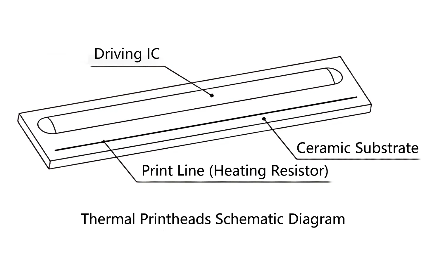
The core component of a thermal printhead is the print line, which consists of a row of heating resistors. Theoretically, these heating resistors all have the same resistance, arranged closely with densities ranging from 200 dots per inch (dpi) to 600 dpi. When a certain current passes through these heating resistors, they rapidly generate high temperatures. Under a specific pressure, when the media coating comes into contact with these heating resistors, the temperature rises rapidly within a short period, causing a chemical reaction in the media coating and displaying colors.
Basic Operating Principles
The fundamental working principle of a thermal printhead is to control the conduction of some or all heating resistors through a driving IC. The principle is illustrated in the diagram below. When current flows through a heating resistor, the energy generated by the heating resistor is the work done by a portion of the current, with power denoted as P. Additionally, work is done as the current flows through, assuming a power of PL. The sum of these two parts is denoted as P0. If the heating time is represented by Ton (in milliseconds), the printing energy can be calculated using the formula P * Ton, with the unit in mJ/dot.

Resolution of Thermal Printheads
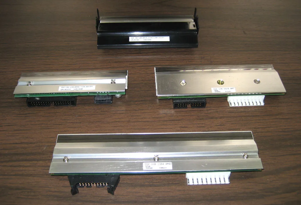
Resolution refers to the number of heating points per inch or per millimeter along the direction of the print line, measured in dots per inch (dpi) or dots per millimeter (dots/mm). The resolution is determined during the manufacturing process of the printhead by the photomask. The most commonly used resolutions are 200 dpi and 300 dpi, both of which meet the requirements of the majority of applications. Different series of printheads may have varying printing width ranges.
Example Illustration
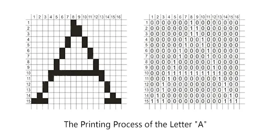
Taking the letter A as an example, it can be broken down into a 16×15 dot matrix of pixels, as shown in the diagram. Each heating resistor corresponds to one pixel during printing. By inputting data as 0 or 1 to control the on/off state of the driving IC, specific points are heated or not heated (0 represents no printing, 1 represents printing). For instance, if the input data for the first row is 0000000100000000, printing occurs in the 8th column of the first row. Similarly, inputting 0000000110000000 for the second row results in printing in the 8th and 9th columns of the second row. This process continues until the 15th row, eventually producing the complete letter A.
Very well written. Thank you.